3-Element PVC Yagi Antenna
A hand-built directional Yagi designed for the GMRS band (462–467 MHz). PVC boom, 26 AWG copper wire elements, half-wave split dipole driven element. Tuned to SWR 1.5 through iterative trimming. Field-tested at 4 miles with Radioddity GM30 Plus radios.
Planning
The goal was a directional antenna for GMRS — a modest gain improvement over the stock rubber duck antennas on handheld radios, with some front-to-back directionality useful for point-to-point communication. The Yagi was the natural choice: a 3-element design offers meaningful gain with a manageable physical size at UHF frequencies, and the math is well-established.
The GMRS band sits between 462 and 467 MHz, so the design was centered on 464.5 MHz. At that frequency a full wavelength is approximately 25.4 inches, making the antenna compact enough to build with common hardware. PVC tubing was used for the boom for its availability, low cost, and ease of drilling element holes. 26 AWG copper wire was used for all three elements.
Element lengths were calculated from standard Yagi formulas, then adjusted for the expected velocity factor reduction caused by the PVC boom running parallel to the elements. The reflector was left at the free-space calculated length. The driven element and director were trimmed empirically to achieve the target SWR.
Design Calculations
All element lengths derive from the free-space wavelength at the center frequency, scaled by standard Yagi element ratios and adjusted for the PVC velocity factor.
Element Layout
Element widths are proportional to length. The center dot on the driven element marks the feedpoint. Signal propagates in the direction of the director (downward in the diagram above).
Build
Boom preparation
PVC tubing cut to boom length. Three holes drilled at the calculated element spacing positions to pass the copper wire elements through perpendicularly.
Reflector installation
26 AWG copper wire cut to the calculated reflector length (12.97 in) and threaded through the rearmost boom hole. The reflector was left at the calculated dimension and not adjusted during tuning.
Driven element — split dipole
The driven element is a center-split half-wave dipole, with the two halves fed at the gap. Starting length was set to the velocity-factor-adjusted value. Iterative trimming was required to bring SWR down to 1.5 — the element consistently measured high and needed significantly more shortening than anticipated.
Director installation and trimming
Director installed at the forward boom position. A director longer than the driven element would behave as a reflector, so it was intentionally cut shorter than the driven to ensure forward directionality. The reflector was left untouched throughout.
SWR verification
Final SWR measured at 1.5 across the GMRS band. Acceptable for the application — less than 4% of forward power is reflected at this ratio.
Build Photo
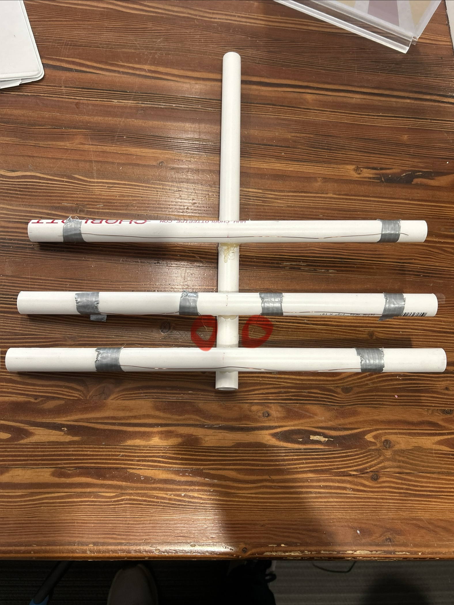
Findings
The driven element needed to be shortened significantly beyond the velocity-factor-adjusted calculated length before SWR came down to target. This is consistent with the PVC boom running parallel to and in close proximity to the element — the dielectric constant of PVC lowers the effective velocity factor further than the nominal 0.95 estimate, shifting the resonant length downward.
This is expected behavior for wire-on-PVC construction and not a flaw. It does mean that calculated starting lengths for this type of build should be treated as upper bounds, with empirical trimming required to finalize.
Tested at approximately 4 miles between a mobile unit and a stationary Radioddity GM30 Plus indoors. At that range with the mobile radio's battery running low, rotating the antenna toward the stationary unit produced a noticeable but modest improvement in signal quality compared to off-axis orientation.
The urban environment introduces significant multipath — signals arrive from multiple reflected paths rather than a single line-of-sight direction, which compresses the apparent front-to-back ratio of any directional antenna. The result is consistent with the antenna working as designed; the environment limited how clearly the directionality could be isolated.
Next Steps
The antenna performed adequately for a first build. The primary areas for improvement are mechanical — a more rigid element mounting method would improve repeatability and make re-tuning less tedious. A ferrite bead or simple choke balun at the feedpoint is worth adding to reduce common-mode current on the feedline, which can distort the pattern and affect SWR.
Testing in a more open environment, away from urban multipath, would give a cleaner read on actual front-to-back ratio and confirm whether the directionality holds up over distance with a clear line of sight.
Design Notes & Corrections
After completing this build, a review of the element spacing revealed a meaningful deviation from standard Yagi design practice. The antenna was tuned to 467 MHz (upper edge of the GMRS band) rather than the 464.5 MHz center, and the boom hole positions were drilled at non-standard intervals. The element lengths and SWR result are valid, but the spacing geometry differs from what the design calculations assumed.
The reflector-to-driven spacing of 3 inches is approximately 40% shorter than the standard 0.20λ recommendation for 467 MHz. Tight reflector spacing raises the feedpoint impedance and pushes the driven element's resonant behavior, which is likely why the element required significantly more trimming than calculations predicted. SWR was ultimately brought to 1.5 through empirical trimming, but the impedance match is less ideal than it would be at the standard spacing.
The driven-to-director spacing of approximately 2.3 inches (derived from a total boom of 5.3 in minus the 3 in reflector–driven gap) is about 39% shorter than the standard 0.15λ. A director this close to the driven element has a stronger mutual coupling effect, which tends to detune both elements and reduce the front-to-back ratio. This is consistent with the marginal directionality observed in field testing.
The antenna does work — SWR is acceptable and some directional effect was measured in the field. However, the compressed boom means it is not achieving the ~7–8 dBd gain a correctly spaced 3-element Yagi at this frequency would produce. The primary consequence is reduced front-to-back ratio and lower forward gain compared to the design target.
For a corrected v2 build at 467 MHz, the boom holes should be drilled at 5.06 in (reflector → driven) and 3.79 in (driven → director), for a total boom length of approximately 8.85 in.