Colpitts RF Transmitter
A discrete-component RF transmitter built around a Colpitts oscillator, adapted from Professor Aaron Danner's design and re-engineered around available lab components. Bench-tested with an SDR to confirm carrier generation, drift behavior, and harmonic content.
Overview
I've always been interested in the practical side of RF engineering, and earning my Amateur Extra license only deepened that. After learning about oscillators and transistor circuits in class, I wanted to move beyond theory and build a working RF transmitter from discrete components.
One aspect of RF engineering that fascinates me is transforming a simple battery-powered circuit into electromagnetic waves that can be detected by a radio receiver. Building this transmitter allowed me to connect classroom concepts like transistor biasing, LC resonance, and positive feedback with a real physical system that produced a measurable radio signal.
Project Inspiration
This transmitter is based on a design presented by Professor Aaron Danner, whose excellent explanation goes beyond simply describing the Colpitts oscillator by showing how it can be implemented as a complete RF transmitter. His discussion of the oscillator, feedback network, and amplifier stage provided the foundation for this project while still requiring careful engineering decisions during implementation.
Rather than duplicating the design exactly, I adapted the circuit using components that were available in my electronics lab and verified that the modified design would still operate correctly.
Engineering Modifications
Although the overall architecture follows Professor Danner's design, several changes were made during construction.
Transistor substitution
The original 2N2222 transistor was replaced with a BC337, whose C-B-E pin configuration better suited my preferred layout.
Component value changes
Several resistor and capacitor values were changed based on component availability in the lab.
Bias re-verification
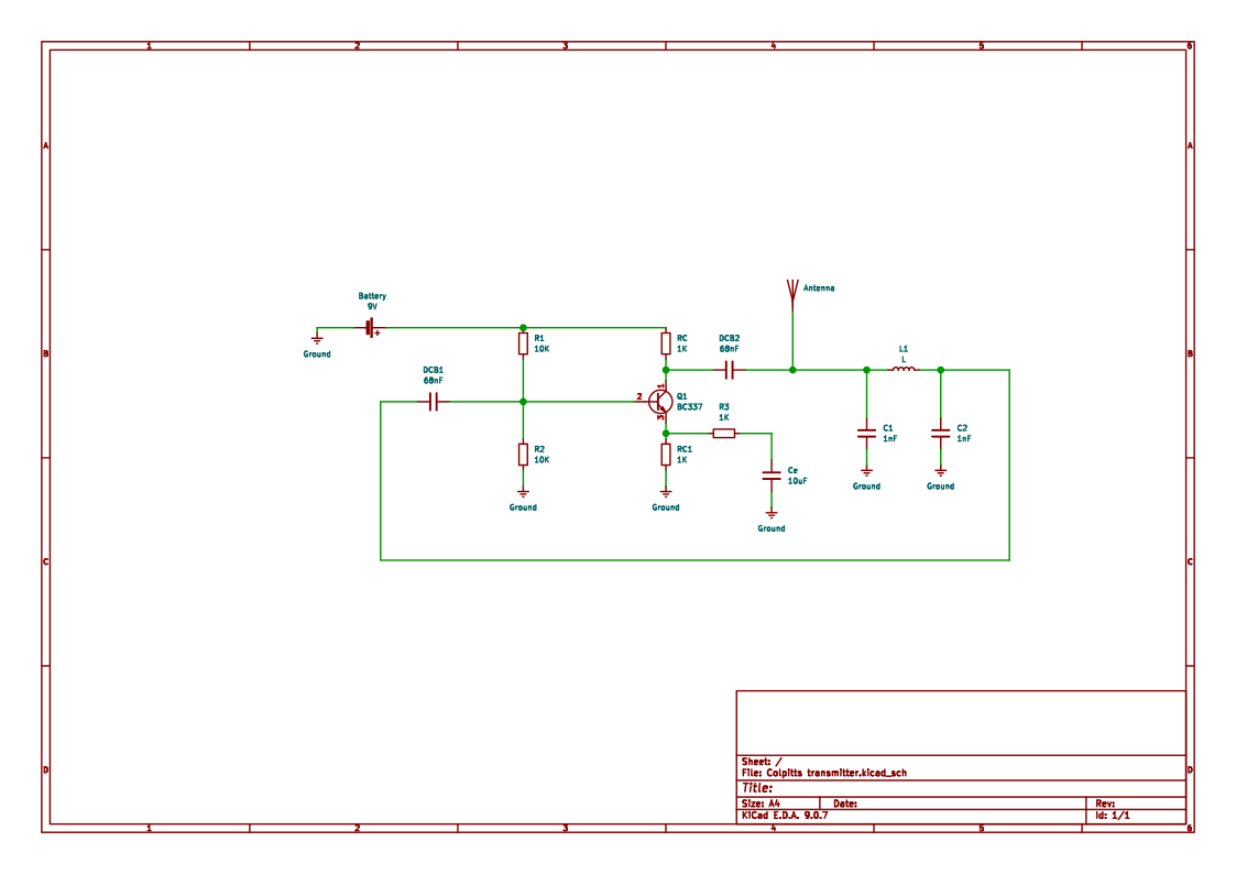
Because these changes altered the transistor bias conditions, I recalculated the DC operating point to verify that the transistor would remain in the proper region of operation and that the oscillator would still satisfy the conditions required for sustained oscillation.
As-built schematic
The schematic below reflects the final circuit that was actually built and tested.
Construction
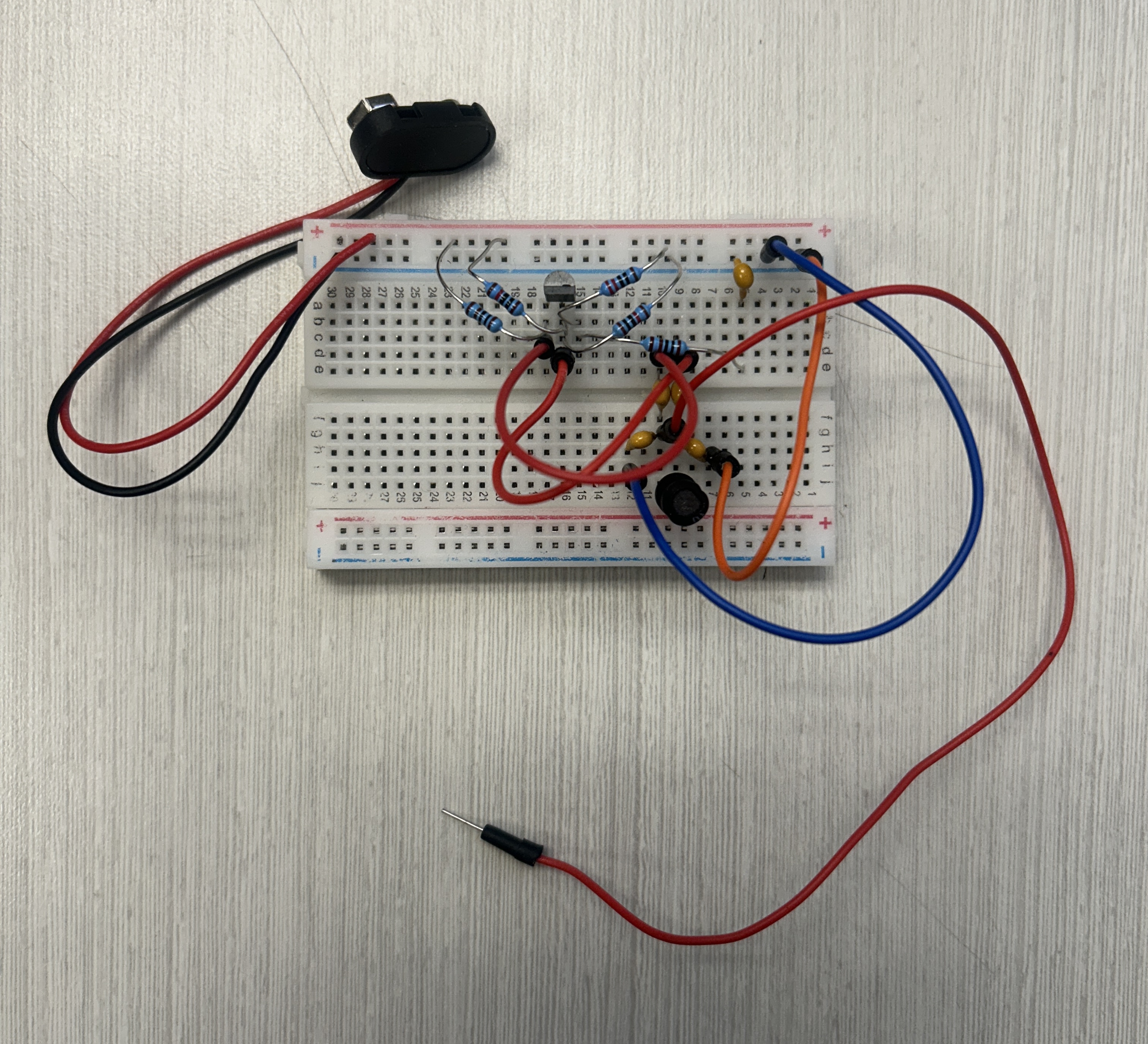
The transmitter was assembled on a solderless breadboard using discrete components. Although breadboards are generally not ideal for RF circuits due to parasitic capacitance and inductance, they provide a convenient platform for experimentation and rapid prototyping.
Testing and Verification
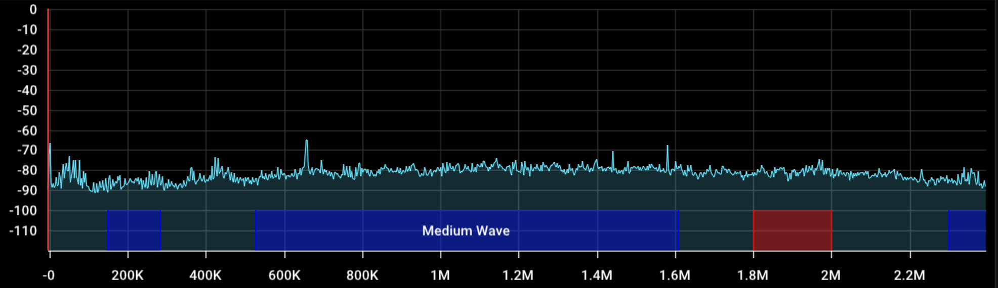
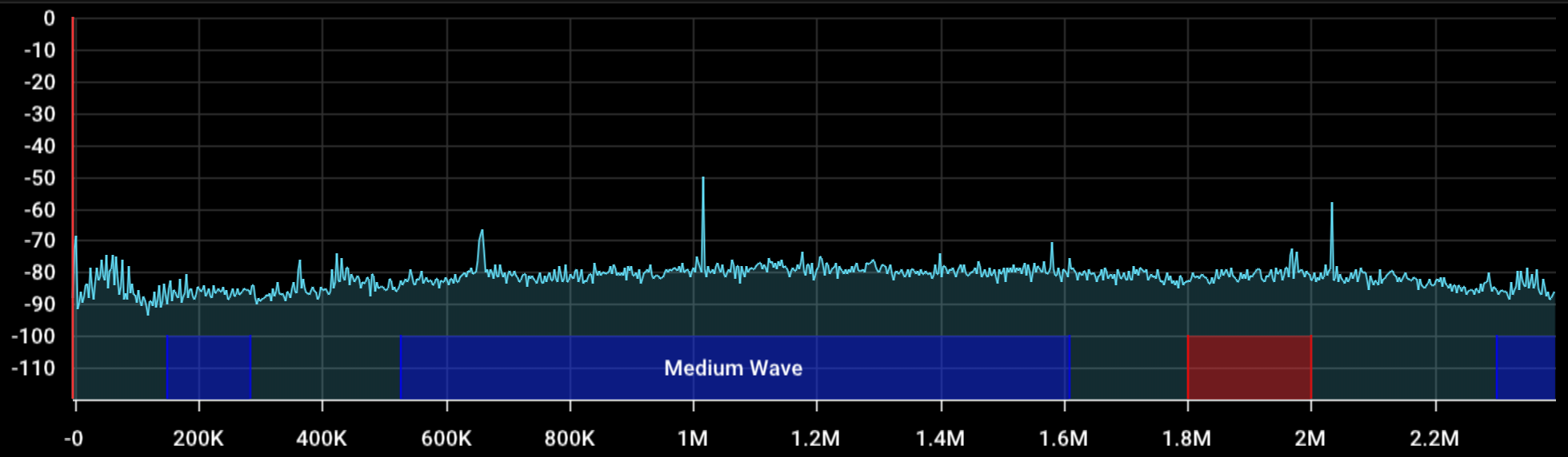
After assembly, the transmitter was tested using my Nooelec Software Defined Radio (SDR). The carrier was successfully received at approximately 1.0–1.1 MHz using the SDR's Q-branch mode.
Because the antenna consisted of nothing more than a short jumper wire, radiation efficiency was extremely poor, resulting in only a very short transmission range.
The project was intended purely as a bench-top experiment and remained well below FCC Part 15 field-strength limits.
What I Learned
This project reinforced several RF engineering concepts that are difficult to fully appreciate through classroom instruction alone.
Why This Project Matters
As an Amateur Extra operator, projects like this also connect directly with my long-term interest in radio communications. Understanding not only how these circuits work but also why they work has provided a solid foundation for more advanced RF projects in the future, including designing transmitters for Morse code experimentation on the amateur bands.